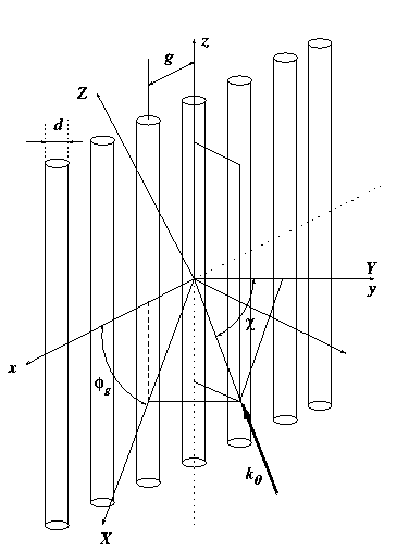
Calculation of Reflection and Transmission Coefficients of Wire Grid
The server of this calculation has not been working from the mid of December 2016 to 22 February 2017. We apologize for this inconvenience.
Now the server resumed. Thank you.
For more details about the calculation method, please refer to Section 2 through Section 4 of
"Transmission and Reflection Characteristics of Slightly Irregular Wire-Grids for Arbitrary Angles of Incidence and Grid Rotation," IEEE Transactions on Antennas and Propagation, vol. 53, no. 1, pp. 250-259, January, 2005.

Warranty Disclaimer: National Institute of Information and Communications Technology (NICT) does not guarantee the correctness and accuracy of the results derived from this Web site, and is not liable for any loss or damage, arising from the use of the result derived from this Web site.
Last updated on March 29, 2005 by Takeshi MANABE, National Institute of Information and Communications Technology (presently with Osaka Prefecture University, Osaka, Japan.)
